
The GS aerials are usually located so that the glide-slope provides a runway threshold crossing height of about 50 ft. Aircraft equipment indicates the displacement of the aircraft above or below the GS. So, even if the navigation data is not accurate enough to tell us which runway was used, knowing the ILS frequency can identify the correct runway.The ILS GS aerials are normally located on the aerodrome they transmit two narrow intersecting beams, one slightly below the required vertical profile and the other slightly above it which, where they intersect, define the "on GS" indication (see Figure 2). We then look up this frequency in our airport database and the match tells us which runway the aircraft landed on. We can look at the ILS Frequency signal for that approach and any valid data will correspond to a possible ILS source. This is how the pilot selects his runway without seeing the airfield. When the aircraft is approaching an airport with parallel runways, the ILS transmitters for the two runways will always be on different frequencies. Any frequencies that are not appropriate for that navigation aid are masked out, leaving just the valid frequencies left. Therefore there are two derived parameters and from each we pass in both the ILS/VOR Frequency and the type of navigation aid. In fact, we want to know the VOR Frequency or ILS Frequency so that we can use them separately. You might expect us to look at the frequency and return the type of signal being tuned, but that does not make it easy to use the resulting signal. The array fours has values of 0 or 1 for VOR sources and 2 or 3 for ILS sources. It boils down to the neat algorithm fours = np.ma.round(array * 20) % 4 to separate out the signals.

This is where the library routine filter_vor_ils_frequencies comes in. It won’t be a surprise to learn that the recorded parameter on the FDR is often the ILS/VOR Frequency, and before we start to use this, we need to be able to discriminate which source it came from. To make life more interesting, they are in pairs thus:

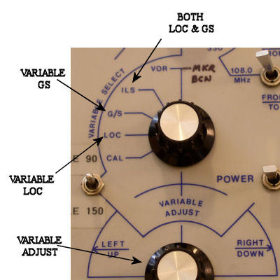
For each ILS localizer signal there is a matching ILS glideslope frequency, so the pilot only tunes the localizer and the glideslope is tuned automatically to match. The top part of this range, from 112.0MHz to 117.95MHz, is only used by VOR transmitters, but the lower range, from 108MHz to 111.95MHz, is used by VOR and ILS Localizer signals. The VOR and ILS Localizer signals are in the range 108MHz to 118MHz, in steps of 0.05MHz. To make life more interesting still, the frequencies used are interleaved. Some of the frequency range is used only by VORs, but some of the range is shared. Now, ILS and VOR systems were designed at about the same time, and use the same range of radio frequencies. The frequency that the receiver has been tuned to is stored in Binary Coded Decimal format (see blog “Top Tip for BCD Decoding”). In many cases we are also provided with the ILS marker beacon flags to show when the aircraft is passing over the Outer, Middle and Inner markers. Looking at the ILS signal, the data recorded on the FDR is a combination of the localizer (lateral) signal, the glideslope (vertical) signal and the frequency that the ILS is tuned to. The reason I have mentioned both systems here will become apparent soon, for those of you who have not spotted the link already… Recorded Data Quite the best description of an ILS that I have seen is available at, and similarly is good for VORs, so please wander over to those sites if you would like to know more about these systems. Two of the key navigation sources, are the Instrument Landing System (ILS) and VHF Omnidirectional Range (VOR).

In fact, the frequency range has not changed since the Second World War when aircraft navigation systems were first being installed. Well, OK, nowadays the flight management system does some computer wizardry making digital signals ping around the aircraft, but still at some point a good old-fashioned radio receiver is still being tuned. When the pilot selects a navigation source, he tunes the receiver to the appropriate frequency for that source. Others are little “helper” functions that come in handy and it is one of these that I will take a look at today. Some of the routines are straightforward mathematical algorithms like integration, differentiation or filtering arranged in a configuration that makes them easy to use with the POLARIS parameter representation.
#LOCALIZER VS VOR FREQUENCIES SOFTWARE#
As readers of this blog will have gathered, the POLARIS analysis software is released as Open Source code, and included in this codebase is a library of useful routines.


 0 kommentar(er)
